Sensory Systems · Unit 8: Integration and repair
Restoring Senses: Implants, Prostheses and Optogenetic Vision
Why does a cochlear implant with up to 22 contacts stop helping some listeners at 8 to 10 channels, and why does the same strategy give pixel-like vision so rarely in the eye? This lesson reads human trials of cochlear, retinal, optogenetic and touch interfaces by design, participants and measured outcome. Afterwards you can read a single-participant improvement, separate a device's native resolution from its enhancements, and say what a single-arm trial can and cannot show.
Watch first A Contact Is Not a Channel · 2:54
A modern cochlear array carries 12 to 22 contacts, yet in one study of adults, speech scores stopped improving at 8 to 10 channels. What is a channel, and why does the same engineering idea fail to give pixel-like vision?
A prosthesis is a claim about a code: that if you put the right pattern of activity into surviving neurons, the brain will read it as a sense. This lesson takes four devices and one rule of thumb. For each device, read the design, the participants and the measured outcome, and nothing more. It is about mechanisms and evidence, not about what any person should do.
Borrowing a map: why place coding is kind to engineers
The hearing and balance lesson gave you the cochlea as a frequency map. That map is what a cochlear implant borrows. The device bypasses damaged sensory structures and excites auditory-nerve neurons directly with current. Clinical maps assign higher frequencies to more basal contacts and lower frequencies to more apical ones (Berg and colleagues, 2020, postlingually deafened adults), which turns the place code into an addressing scheme.
Three counts get confused, and it helps to keep them apart. A contact is a piece of hardware on the array. A channel, in this context, is a band of frequency information. An independently accessible neural population is what you would need for the channels to be truly separate. Neighbouring contacts produce overlapping electric fields, called channel interaction, so many contacts do not give the same number of independent channels.
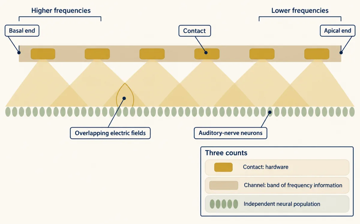
The data show how much the answer depends on the listener and the test.
- In 18 adult implant users, with electrode position measured by computed tomography, speech recognition reached an asymptote at 8 to 10 channels in groups with straight arrays and with translocated precurved arrays. The tests were acute. The same group reported continuing gains beyond 8 to 10 channels for well-placed precurved arrays (Berg and colleagues, 2019), so the plateau depends on array type and placement.
- In seven adults (eight ears) using experimental maps, going from 20 active electrodes to 8 worsened the speech-in-noise threshold by about 2 dB signal-to-noise ratio on average (Schvartz-Leyzac, Zwolan and Pfingst, 2017). The authors concluded that adult listeners could benefit from more than eight spectral channels.
Both can be true. A plateau in one test, in one group, with one array placement does not mean the extra contacts do nothing, and a benefit under hard conditions does not mean each contact is independent. There is no single channel number for all listeners.
Keep listening conditions apart too. In 96 adults (median age 71 years) who used a hearing aid before implantation, the marginal mean improvement in CNC word recognition at six months was 40.5 percentage points, with the implant plus a hearing aid in the other ear (Buchman and colleagues, 2020). In the implanted ear alone, 87 of the 96 improved by more than 15 percentage points. These are different tests, so 40.5 is not an implant-alone number.
Why a retinal electrode does not make a pixel
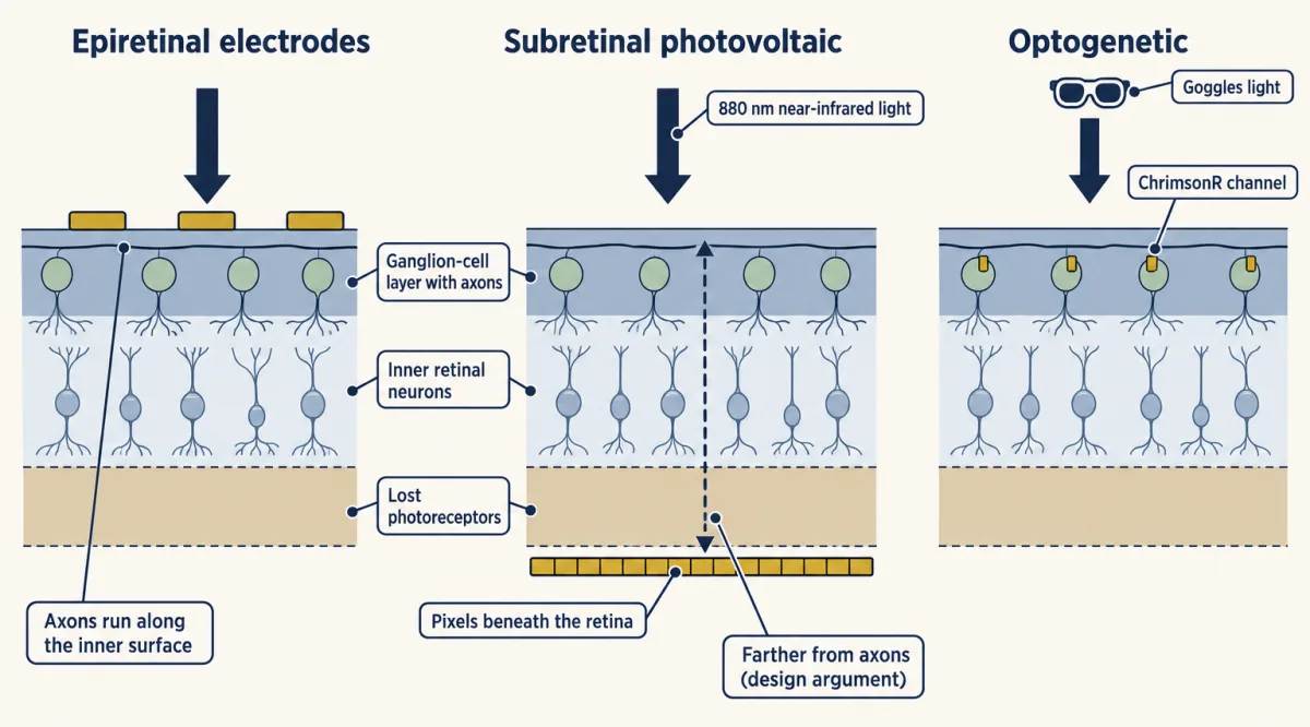
An eye is a camera, so the tempting design is a grid of electrodes that makes a grid of dots. The Argus II tried it: a camera converted images into stimulation patterns for an array of 60 electrodes on the inner surface of the retina (epiretinal), in 30 adults with end-stage outer-retinal degeneration (29 with retinitis pigmentosa, one with choroideremia) in a prospective trial (da Cruz and colleagues, 2016). The maker’s fiscal-2019 annual report states that production of the device ceased during a move to a different product, with later sales limited to finished inventory. That is a production decision. This lesson makes no claim about current availability.
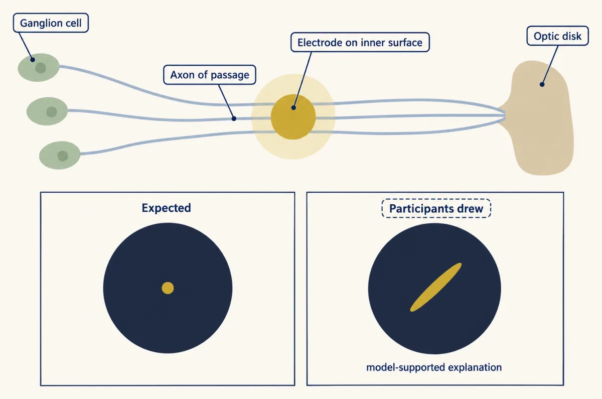
The reason dots did not appear is in the anatomy you met in the retina. The axons of ganglion cells run across the inner surface of the retina toward the optic disk, and that inner surface is where an epiretinal electrode sits (over the macular retina in these implants). Beyeler and colleagues (2019) asked four adults with severe retinitis pigmentosa (one Argus I and three Argus II implants) to draw what they saw when single electrodes were stimulated. The drawings were often elongated or distorted. A model that traces axon pathways across the retina accounted for the shapes: current excites axons of passage, and the percept follows the places those axons normally serve. That is a model-supported explanation of the drawings, not a direct recording of the axons.
One electrode therefore does not make one pixel, and a simulation that draws a clean grid of dots overstates what the implant user sees.
Photovoltaic implants take a different route. In the PRIMA design, a camera image is projected into the eye at 880 nm near-infrared light at 30 Hz. Photovoltaic pixels under the retina convert that light into current that stimulates nearby inner retinal neurons. Brightness is set by pulse duration, from 0.7 to 9.8 ms, at a peak irradiance of 3.5 mW per square millimetre. Because the pixels sit beneath the retina instead of on its inner surface, they are thought to be farther from the axon layer, though that is a design argument and not the finding of a controlled comparison.
In the first clinical report, five adults over 60 with advanced atrophic age-related macular degeneration and no foveal light perception received a chip of 378 pixels, each 100 micrometres across (Palanker and colleagues, 2020). The three people with optimal chip placement reached prosthetic acuity of 20/460 to 20/550.
The later PRIMAvera study (Holz and colleagues, online 2025, 2026 issue of the New England Journal of Medicine) was open-label, nonrandomized and single-arm. It enrolled adults with geographic atrophy due to age-related macular degeneration, aged at least 60 years (mean 78.9), and implanted 38 of them. At twelve months 32 were assessed. The primary endpoint was an improvement of at least 0.2 logMAR in prosthetic acuity measured with the PRIMA glasses, where participants could adjust zoom, compared with baseline. That is a drop of 0.2 in the log of the minimum angle of resolution, about a 1.6-fold finer limit. In 26 of the 32 assessed participants the endpoint was met; the authors’ multiple-imputation estimate for all 38 was 80 percent. Nineteen participants had 26 serious device- or procedure-related events over the twelve months, and mean natural peripheral acuity did not change significantly.
Read the acuity carefully. Mean implant-resolution acuity without zoom or image processing was 1.32 logMAR. The Snellen denominator is 20 times 10 to the power of the logMAR value, so 20 x 10^1.32 is about 417, or 20/417. Participants could also adjust the zoom from 1 to 12 times during acuity testing, and a zoom-assisted chart score measures the implant plus a magnifier. Native resolution and zoom-assisted reading are separate measurements. Neither number applies to people with other retinal diseases.
- Snellen = 20 × 10logMAR
- Fold change, 10Δ (finer minimum angle)
- Acuity after the change
- Endpoint responders, two denominators
In this sketch: the standard logMAR-to-Snellen conversion only, with no zoom or image-processing arithmetic. The 1.32 and the 0.2 endpoint come from adults with geographic atrophy (mean age 78.9) in an open-label, single-arm study (Holz and colleagues); the band is from five adults in the first clinical report (Palanker and colleagues).
Rule to keep: convert with 20 × 10logMAR, keep native implant resolution apart from zoom-assisted scores, and quote responders with both denominators.
Putting the signal in with light instead of current
A third approach changes the cells instead of adding electrodes. In an optogenetic therapy, a viral vector makes surviving cells express a light-gated channel. The photoreceptor adaptation and degeneration lesson covered why photoreceptors are lost in retinitis pigmentosa; the actuators come from the cell hacking toolkit.
Sahel and colleagues (2021, Nature Medicine) combined an intraocular vector encoding the red-shifted channel ChrimsonR with engineered light-stimulating goggles in one adult with blindness from retinitis pigmentosa. The goggles activated transduced retinal ganglion cells. Because those cells are the retina’s output, no upstream retinal processing is left to do the work, so the goggles must supply the transformation of the scene into light patterns. That follows from the design.
The tests compared conditions. With the treated eye and the goggles, the patient perceived, located, counted and touched objects. After the injection and without the goggles, the patient did not detect objects. EEG showed object-related activity above visual cortex during perception. The with-goggles and without-goggles comparison is the informative one: it shows that, in this patient and in these tasks, the response depended on the goggle light. It does not show restored normal vision, and one patient cannot establish how often this works.
A later open-label trial of a ganglion-cell-directed ChrimsonR vector with goggles enrolled ten adults with advanced retinitis pigmentosa (Sahel and colleagues, N. Engl. J. Med., 2026). Its primary outcome was safety. Light sensitivity increased in seven of the ten, but the protocol did not prespecify what size of improvement would count as clinically meaningful. Treat it as added evidence of feasibility, not proof of useful sight.
Touch written into a nerve or a cortex
Touch can be written in at the peripheral nerve or at the cortex. For the natural afferents being imitated, see touch and pain and sensory coding; the course lessons on vibration corpuscles and the dorsal horn show the code in more detail.
Peripheral nerve. Tan and colleagues (2014) tested nonpenetrating cuffs on residual nerves in two men with upper-limb amputations, in laboratory sessions. Stimulation produced touch in the phantom hand. The responses were repeatable and stable for 16 and 24 months. Patterned stimulation produced sensations the participants described as natural, and artificial touch helped them manipulate delicate objects with the prosthesis. Two participants and subjective ratings do not establish normal touch.
Cortex. Flesher and colleagues (2016) stimulated primary somatosensory cortex through microelectrode arrays in one man with a long-term cervical spinal cord injury. Stimulation evoked sensations projected to the hand, and changing the amplitude graded the perceived intensity. Many percepts remained stable for months. In the 2021 follow-up, a man who was 28 at implantation controlled a robotic arm by decoding motor cortex, while somatosensory stimulation provided tactile feedback. The median task time fell from 20.9 s without feedback to 10.2 s with it, mainly through less time spent trying to grasp objects.
Worked problem: read a single-participant improvement.
- Absolute reduction = 20.9 s - 10.2 s = 10.7 s.
- Percentage reduction relative to the no-feedback median:
percentage reduction = 100 x (20.9 - 10.2) / 20.9 = 100 x 10.7 / 20.9 = 51.2 percent
- Scope: this compares two medians from one participant. It is not a mean paired effect and not a population effect. Repeated trials in one person are not independent replicates. The authors checked practice and decoder effects with 23 earlier sessions in which feedback was absent or unreliable and a daily decoder-only task, but the result still comes from one person and supports the usefulness of feedback in that person.
Features of touch. Valle and colleagues (2025) studied two adults with cervical spinal cord injury who had arrays in the hand representation of Brodmann area 1. Spatially patterned multi-electrode stimulation evoked sensations of tactile edges, and spatiotemporal patterns evoked apparent motion with controllable speed and direction. This widens what can be written in. It does not show that every quality of touch has been restored.
Biomimicry as a design rule, and its evidence
The strategy running through these studies is biomimicry: reproduce the task-relevant features of the natural neural code, then test the percept and the behaviour. The place map in the cochlea and the natural-feeling patterns in touch are examples. Hobbs and colleagues (2025) tested it directly in three adults with cervical spinal cord injury and S1 arrays. They compared cortical stimulation with mechanical indentation delivered to residual sensate hand regions. Simple single-electrode biomimetic stimulation felt more like the mechanical reference than the non-biomimetic pattern did on 32 percent of tested electrodes, and advanced four-electrode biomimetic stimulation did so on 75 percent of tested electrode groups. Biomimetic trains also needed less charge for intensity-matched sensations. The denominators differ (electrodes against electrode groups), so the two percentages are not a controlled head-to-head comparison.
This supports biomimicry as an evidence-backed strategy. It is not a proven law that performance depends on how exactly the code is reproduced, and it says nothing about ranking one disorder’s prosthesis against another’s: the studies cited here do not compare cochlear and retinal devices head to head.
Design problem
A company reports that its visual implant improved acuity in a single-arm trial. Design the study you would want before believing the claim, and interpret the published numbers from PRIMAvera.
One way to do it
Start with what a single arm confounds: surgery, device use, training and time all change together. So ask for:
- A prespecified primary endpoint with a stated minimum change (PRIMAvera used at least 0.2 logMAR).
- A comparison group, such as an untreated or deferred-implantation group, so the change can be separated from practice and time.
- Masked assessors for acuity testing where the device allows.
- The full denominator. Of 38 implanted, 32 were assessed at twelve months, and 26 of those 32 met the endpoint. That is 26/32 = 81.3 percent of those assessed, but if the six unassessed participants are counted as not meeting the endpoint, it is 26/38 = 68.4 percent. Both numbers belong in the report, with an account of why the six were missing.
- Adverse events beside the benefit: 26 serious device- or procedure-related events in 19 participants.
- Native implant resolution (mean 1.32 logMAR, about 20/417) reported apart from zoom-assisted reading, plus the unchanged natural peripheral acuity.
- A statement of scope: adults with geographic atrophy at a mean age of 78.9 do not stand for all blindness, and one trial cannot compare this device with an implant for another sense.
How we measure it
Phosphene drawing with axon-pathway modelling
Implant users draw the shape they see when a single electrode is stimulated, and the drawings are compared with a model that traces ganglion-cell axons across the retina. It tests whether percept shape follows neural geometry.
Intracortical microstimulation
Microelectrode arrays in cortex deliver small current pulses, and the participant reports where the sensation is, how strong it is and what it feels like. Varying amplitude, pattern and electrode choice shows which features of touch can be written in.
Optogenetic gene therapy with stimulating goggles
A viral vector makes surviving retinal neurons express a light-gated channel, and goggles supply the light. Testing with and without the goggles, before and after injection, separates the effect of the channel from the effect of the device.
Speech testing in implant listeners
Word recognition (for example CNC words) or speech-in-noise thresholds are measured under a stated listening condition, such as implant ear alone or implant plus a hearing aid. Scores are only comparable within one condition.
Finish line
Test yourself
8 questions
Practice and MCAT-style, with explained answers.
That's the last lesson
Back to all lessons
Pick another topic, or revisit one you want to firm up.
All lessons →